Contents
List of
publications
This thesis consists of an overview and the following publications:
- Jarmo Ruohonen, Paolo Ravazzani and Ferdinando Grandori. An
analytical model to predict the electric field and excitation zones due to
magnetic stimulation of peripheral nerves. IEEE Transactions on Biomedical
Engineering 42, 158-161, 1995.
- Jarmo Ruohonen, Paolo Ravazzani, Jan Nilsson, Marcela
Panizza, Ferdinando Grandori and Gabriella Tognola. A volume-conduction
analysis of magnetic stimulation of peripheral nerves. IEEE Transactions on
Biomedical Engineering 43, 669–678, 1996.
- Paolo Ravazzani, Jarmo Ruohonen, Ferdinando Grandori and
Gabriella Tognola. Magnetic stimulation of the nervous system: induced
electric field in unbounded, semi-infinite, spherical, and cylindrical media.
Annals of Biomedical Engineering 24, 606–616, 1996.
- Jarmo Ruohonen, Marcela Panizza, Jan Nilsson, Paolo
Ravazzani, Ferdinando Grandori and Gabriella Tognola. Transverse-field
activation mechanism in magnetic stimulation of peripheral nerves.
Electroencephalography and clinical Neurophysiology 101,
167–174, 1996.
- Jarmo Ruohonen, Paolo Ravazzani, Risto Ilmoniemi, Giuseppe
Galardi, Jan Nilsson, Marcela Panizza, Stefano Amadio,
Ferdinando Grandori and Giancarlo Comi. Motor cortex mapping with
combined MEG and magnetic stimulation. Electroencephalography and clinical
Neurophysiology Supplement 46, 317–322, 1996.
- Jarmo Ruohonen, Juha Virtanen and Risto Ilmoniemi. Coil
optimization for magnetic brain stimulation. Annals of Biomedical
Engineering 25, 840–849, 1997.
- Jarmo Ruohonen and Risto Ilmoniemi. Focusing and targeting
of magnetic brain stimulation using multiple coils. Medical &
Biological Engineering & Computing 36, 297-301, 1998.
- Risto Ilmoniemi, Juha Virtanen, Jarmo Ruohonen, Jari Karhu,
Hannu Aronen, Risto Näätänen and Toivo Katila. Neuronal responses to magnetic
stimulation reveal cortical reactivity and connectivity. NeuroReport
8, 3537-3540, 1997.
List of
abbreviations
CT Computed tomography
EEG Electroencephalography
EMG
Electromyography
EP Evoked potential
ERP Event-related potential
ES
Electrical stimulation
FEM Finite element method
fMRI Functional magnetic
resonance imaging
MEG Magnetoencephalography
MEP Motor-evoked
potential
MNE Minimum-norm estimation
MRI Magnetic resonance imaging
MT
Motor threshold
NIRS Near-infrared spectroscopy
PET Positron emission
tomography
PNS Peripheral nervous system
rTMS Repetitive transcranial
magnetic stimulation
SPECT Single photon emission computed tomography
TCES
Transcranial electrical stimulation
TMS Transcranial magnetic
stimulation
3D Three-dimensional
1 Introduction
The use of non-invasive neuroimaging has increased explosively in recent
years. Details of the functioning of the human brain are revealed by measuring
electromagnetic fields outside the head or metabolic and hemodynamic changes
using electroencephalography (EEG), magnetoencephalography (MEG), positron
emission tomography (PET), near-infrared spectroscopy (NIRS) or functional
magnetic resonance imaging (fMRI). This thesis deals with transcranial
magnetic brain stimulation (TMS), which is a direct way of manipulating and
interfering with the function of the cortex, thus complementing conventional
neuroimaging.
Brain stimulation with TMS is achieved from the outside of the head using
pulses of electromagnetic field that induce an electric field in the brain.
TMS has numerous applications in the study, diagnosis and therapy of the
brain. TMS can either excite the cortex or disturb its function. The observed
excitatory effects are normally muscle twitches or phosphenes, whereas in the
"lesion" mode TMS can transiently suppress perception or interfere with task
performance.
The aim of this thesis was to develop physical understanding of magnetic
stimulation and to build models that could provide new insights for utilising
the technique. For this purpose, two principal issues had to be addressed: 1)
macroscopic electromagnetic fields in the tissue, for which models are
developed in Publications I-III, and 2) understanding
of the neuronal responses, considered in Publications IV and V. Then, the
models developed were used as a basis for engineering modifications that would
increase the utility of TMS, the emphasis being on the optimisation of the
stimulating coils (Publication VI) and on the use of multiple coils in a
whole-scalp array (Publication VII). Publication VIII presents the concurrent
use of TMS and high-resolution EEG, showing that the combination is effective
for mapping the functional connections in the brain.
The models and procedures were developed in parallel with the design and
construction of TMS instrumentation for computer-assisted stimulation.
2 Basic principles and history
2.1 Basic principles
Neurones can be excited by externally applied time-varying electromagnetic
fields. In TMS, excitation is achieved by driving intense pulses of current
I(t) through a coil located above the head. The source of
activation is the electric field E induced in the tissue, obtained from
Faraday’s law:
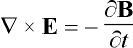 , (1)
, (1)
where B is the magnetic field produced by the coil, given by the
Biot-Savart law:
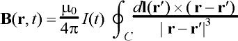 . (2)
. (2)
The integration is performed with the vector dl along the
coil windings C and m0 = 4p´ 10-7 H/m is the permeability of free space.
The pulses of current are generated with a circuit containing a discharge
capacitor connected with the coil in series by a thyristor. With the capacitor
first charged to 2-3 kV, the gating of the thyristor
into the conducting state will cause the discharging of the capacitor through
the coil. The resulting current waveform is typically a damped sinusoidal
pulse that lasts about 300 ms and has a peak value of
5-10 kA. The electrical principles have been
outlined, e.g., by Jalinous [72,73].
Figure 1 summarises the chain of events in TMS. The induced E is
strongest near the coil and typically stimulates a cortical area of a few
centimetres in diameter. TMS pulses cause coherent firing of neurones in the
stimulated area as well as changed firing due to synaptic input. At
microscopic level, E affects the neurones’ transmembrane voltage and
thereby the voltage-sensitive ion channels. Brain imaging tools can be used to
detect the associated electrical currents and changes in blood flow of
metabolism. In motor-cortex stimulation, peripheral effects can be observed as
muscle activity with surface electromyography (EMG). Moreover, there may be
behavioural changes, for instance, impaired task performance.
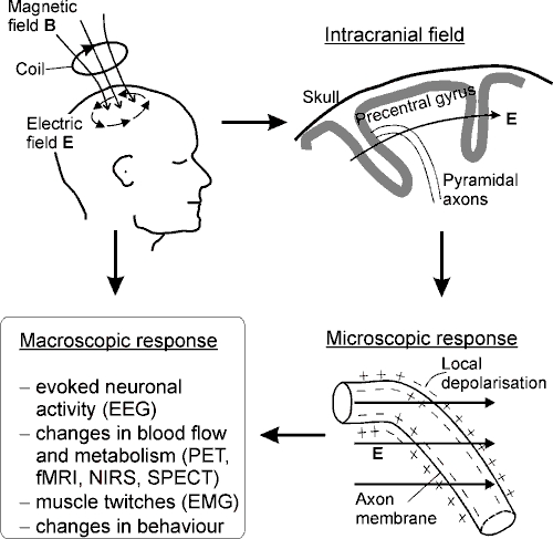
Figure 1. Principles of TMS. Current I(t) in
the coil generates a magnetic field B that induces an electric field
E. The lines of B go through the coil; the lines of E
form closed circles. The upper-right drawing illustrates schematically a
lateral view of the precentral gyrus in the right hemisphere. Two pyramidal
axons are shown, together with a typical orientation of the intracranial
E. The electric field affects the transmembrane potential, which may
lead to local membrane depolarisation and firing of the neurone. Pyramidal
axons are likely stimulated near bends, as illustrated here, but also other
mechanisms exist (see, section 3.2) and other neurones may be stimulated.
Macroscopic responses can be detected with functional imaging tools (EEG, PET,
fMRI, NIRS and SPECT = single photon emission computed tomography),
with surface EMG, or as behavioural changes.
2.2 History of non-invasive brain
stimulation
Stimulation of the exposed human cerebral cortex with electrical currents
was first described by Bartholow in 1874 [11]; the currents elicited movements
of the opposite side of the body. Electrical brain stimulation is today
possible non-invasively using scalp electrodes [96]. However, transcranial
electrical stimulation (TCES) is very painful and hence of limited value.
The first experiments with magnetic stimulation were conducted by
d’Arsonval in 1896 [36]. He reported "phosphenes and vertigo, and in some
persons, syncope," when the subject's head was placed inside an induction
coil. Later, many scientists reported the phenomenon of magnetophosphenes,
that is, visual sensations caused by the stimulation of the retina due to
changing magnetic fields [10,15,41,92,155,159].
Magnetic nerve stimulation was accomplished only several decades
later, first in the frog by Kolin et al. [79] in 1959 and then in the
human peripheral nerve by Bickford and Fremming [17] in 1965. The latter
authors used an oscillatory magnetic field that lasted 40 ms. The
resulting long-lasting activation interval made it impossible to record nerve
or muscle action potentials, and the work was not pursued further. In the
following years, the technique was investigated only occasionally
[68,87,118].
In 1982, Polson, Barker and Freeston [128] described a prototype magnetic
stimulator for peripheral nerve stimulation. They used 2-ms-duration pulses
and recorded, for the first time, motor-evoked potentials (MEPs) obtained by
median nerve magnetic stimulation. In present-day devices, the pulse duration
is typically shorter.
In 1985, the Sheffield group achieved successful transcranial magnetic
stimulation [9] and made the first clinical examinations [6]. TMS proved
valuable for probing the motor pathways: in healthy subjects, stimulation over
the motor cortex causes twitches in hand muscles in about 25 ms, while many
neurological conditions manifest slower conduction. Another important
characteristic of TMS is that it is painless, the subject usually feeling only
a not uncomfortable sensation of scalp being pinched. The encouraging results
led into commercialisation of TMS by Novametrix Ltd. (predecessor of Magstim
Company).
Since 1985, magnetic stimulator technology has remained mostly unchanged.
Whereas early research used circular coils, today devices are usually equipped
also with an 8-shaped, or figure-of-eight coil proposed by Ueno [157]. The
8-shaped coil induces a more concentrated electric field than the circular
coil, resulting in better control of the spatial extent of the excitation.
Another important development is repetitive TMS (rTMS) capable of delivering
trains of stimuli at 1-50 Hz. rTMS was first produced
by Cadwell Laboratories in 1988 and is today one of the most quickly growing
areas of TMS research.
The reader may get a detailed overview of the history and principles of
magnetic stimulation, for instance, from Refs. [5,49].
3 Modelling of magnetic
stimulation
Models of magnetic stimulation are of great importance in the investigation
of the locus, extent and mechanisms of stimulation, in the interpretation of
experiments and in the design of effective instrumentation. Modelling can be
divided into two important separate parts: 1) the computation of the
macroscopic electromagnetic fields due to current in the coil, and 2) the
response of neurones as a result of electrical charges that the macroscopic
field builds up on their membranes.
This section also outlines experimental results about the locus of
activation and about the dominant cellular mechanisms.
3.1 The induced electric field
Generally, the shape of the electric field induced in the tissue depends on
1) the shape of the induction coil, 2) the location and orientation of the
coil with respect to the tissue, and 3) the electrical conductivity structure
of the tissue.
The total electric field in the tissue is the sum of primary and
secondary electric fields, the primary field E1 being
induced by the changing magnetic field B(t) from the coil, as
stated by Eqs. 1 and 2. In conductors, E1 causes a flow of
current J = sE1, s being the conductivity. Any conductivity changes
along the path of the current cause nonuniformity of electric charges, giving
rise to an electrostatic potential V, the negative gradient of which is
the secondary field E2 = –Ñ V. Expressing
B in terms
of the vector potential A, i.e., B = Ñ ´ A, the total E is [70]:
![]() . (3)
. (3)
The potential V obeys Laplace’s equation, Ñ
2V = 0. Equation 3 has
been solved for the unbounded space [54] and for simple conductor shapes such
as the semi-infinite space [42], spheres [43], and infinite-length cylinders
[44,45]. Other shapes and inhomogeneities have been modelled numerically
[23,37,106,139,149,157].
3.1.1 The relationship between TMS and MEG
TMS is the converse of MEG, which uses a number of sensor coils to measure
the magnetic field generated by electrical currents associated with neural
activation. Because of the converse relationship, several results obtained in
connection with MEG have relevance to TMS, and vice versa. The E
induced in the brain by TMS can be obtained using the same formulas that in
MEG give the sensor coil signal due to known intracranial currents
[Publications I-III]. The theoretical link is
constituted by the reciprocity theorem [29,61,80]:
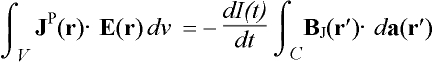 , (4)
, (4)
where BJ is the external magnetic field at r¢ produced by a primary current distribution
JP inside the volume conductor V approximating the
head. Vector da is a vector normal to an arbitrary surface
spanned by the windings of the induction coil C and the current in the
coil is I(t). Both calculations are to be conducted for the same
geometry. The reciprocity holds for linear and inhomogeneous space and for
anisotropic space with symmetric permittivity and permeability tensors [80].
Moreover, it is required that I(t) be of low frequency,
i.e., quasi-static. These conditions can be considered to exist in
magnetic stimulation.
On the other hand, the flux F through an
MEG sensor coil due to an intracranial current JP can be
written in terms of a sensitivity function L, called lead field
for the coil [60]:
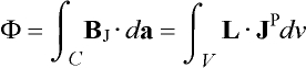 . (5)
. (5)
From Eqs. 4 and 5, the solution for E in TMS is obtained by assuming
that the MEG coil is used for stimulation instead of flux measurement. Driving
the coil with current I(t), the induced field is:
 . (6)
. (6)
The lead field at r can be computed by calculating the flux coupled
into the coil by the magnetic field due to an arbitrary current dipole (a
short element of current) immersed in the tissue at r [60]. This is the
forward problem, which has been solved explicitly for simple conductor
shapes such as spheres [65,148] and spheroids [35].
Primary currents perpendicular to the lead field do not couple flux into
the sensor coil, which prevents localisation of such sources in the brain with
MEG. The converse is true in TMS: no field is induced in directions
perpendicular to the lead field.
3.1.2 Field shaping with multiple coils
With multiple coils, i.e., channels, the TMS excitation field can be
electronically shaped by changing currents in the coils individually (see,
chapter 5.2). Field shaping aims at finding the optimal currents in n
coils to realise a field that is as close as possible to a desired field
configuration P. Publication VII formulates the TMS field-shaping
problem as the minimisation of the norm ò
(E-P)2dv between
P and the actual field E. The resulting optimal coil currents
are then obtained from the column vector J = (dI1/dt, ..., dIn/dt)T
[Publication VII]:
J = -L+J, (7)
where P = (ò P·L1dv, ..., ò P·Lndv)T and
L is a square matrix with elements Lij = ò
Li·Lj dv
(i,j = 1, K , n). The pseudoinverse of L is L†. The resulting E is then
 , (8)
, (8)
where (L†P)i is the ith element of
vector L†P. Eq. 8 is analogous with the MEG minimum-norm
estimate (MNE) of the intracranial current density that best explains the
measured data [60]. Eq. 8 holds also for TCES, provided that electrical lead
fields are used and the coils’ rates of change of current in vector J are replaced by electrode currents.
The field-shaping problem is not generally exactly solvable, there being
infinitely many P that cannot be realized. Therefore, different target
field configurations P can lead to the same solution. MNE is one
possible solution, but not necessarily the best. These conclusions do not
change with the number of coils. When the goal is to minimise the extent of
the stimulating field, search algorithms give better results [Publication
VII], since the mathematical formulation of the MNE procedure implies a
tendency to diffuse solution fields. The great advantage of MNE-based field
shaping is that once L†
is computed for the given coil array, the optimal coil currents for any
P are obtained by simple matrix multiplication.
3.1.3 No 3D focusing
Many interesting studies would emerge if it were possible to focus the
induced E in depth, that is, to obtain a field that is strong in
deep brain structures and weak in the structures above. Unfortunately,
focusing in depth is not possible with any combination of TMS and/or TCES.
Heller and van Hulsteyn [61] have proved mathematically that at quasi-static
frequencies the field is always stronger on the boundary than in the interior
of any volume-conductor compartment with constant conductivity. For
spherically symmetric conductors, the maximum field within the conductor is
always on the outer surface. Coil designs capable of 3D TMS focusing are
occasionally suggested, but doomed to failure.
In non-spherical conductors with varying conductivity, it is possible that
E is maximal in a deep low-conductivity region. Since such regions can
pin the locus of the field maximum, smooth changing of the site of neuronal
excitation is not possible. This means that focusing in depth can not be
realised.
3.1.4 Spherical head model
In MEG, a widely used approximation of the conductivity geometry of the
head is the spherical model. It has been shown that the spherical model is
appropriate for superficial parts of the head [59]. Since TMS can not
effectively reach deep structures and can not be focused in depth, it follows
from the reciprocity that the spherical model must be applicable also to TMS.
The spherical model must be used so that the sphere fits the local radius of
curvature of the inner surface of the skull near the area of interest. The
mathematical formulation is found in Refs. [61,65,148].
Publication III examined the effects of spherical boundaries. Fig. 2
displays the magnitude of the induced E in the unbounded and sphere
models for circular and 8-shaped TMS coils. The spherical model is seen to
decrease the strength of E, but the distribution of the field is
similar in the two models. When the circular coil is tilted erect above the
head (Fig. 2b, coil axis tangential to the sphere surface), the electric field
induced in the sphere is much smaller than in the unbounded model. In the
absence of the boundary the maximum field value is the same for the tangential
and erect coils (Figs. 2a and 2b, top). The boundary effects disappear for any
coil whose axis passes through the sphere centre [29,61]. This is the main
reason why motor responses are more easily elicited with a circular coil flat
on the vertex than with other orientations.
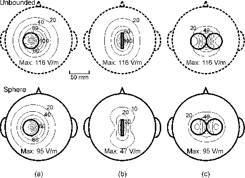
Figure 2. Contour maps of the strength of E on an
8-cm-radius spherical surface for the unbounded (top) and spherical medium
(bottom). (a) Tangential, laterally shifted circular coil; (b) erect circular
coil; and (c) 8-shaped coil. Projections of the coils are depicted with thick
continuous lines. The diameter of the coils was 40 mm and
dI/dt = 108 A/s. The coils had 10 turns. The
peak value of E is given below each plot. The depth of the spherical
surface below the coil was 15 mm.
The Ampère-Laplace law, which is the continuous
counterpart of the Biot-Savart law in Eq. 2, implies
that in all axially symmetric conductor shapes the induced E along any
rotational axis vanishes on that axis [Publication I]. This means that
E is never oriented towards the centre of the sphere.
3.1.5 Models of the limbs and the spine
Cylinder-shaped volume conductors can be used to model limbs. Publications
I and II derived analytical solutions to E and its gradient ¶ Ex/¶ x
in a prolate spheroid as well as in unbounded and semi-infinite conductors. An
analytical solution is available also in the infinite-length circular cylinder
[44,45]. Finite-length cylinders have been analysed numerically
[37,115,139].

Figure 3. The induced ¶
Ex/¶ x in unbounded (top) and
prolate spheroidal (bottom) models due to circular and 8-shaped
coils. The field plane was 10 mm below the coil plane. Contour step is
0.5 kV/m2. The zero contours are dotted and the negative
contours dashed. Projections of the coils are depicted with thick continuous
arcs. Both wings of the 8-shaped coil comprised 5 turns of 50 mm in radius;
the edge-tangential coil had 10 turns. The spheroid’s radius was 40 mm and
its length 1 m and dI/dt = 108 A/s.
The inserts show the geometry, coil orientations and field plane (dark
rectangle). Adapted from Publication II.
In peripheral stimulation, an important activating feature of E is
thought to be its gradient along the axon, ¶
Ex/¶ x (chapter 3.2). Fig. 3
dis-
plays the ¶ Ex/¶ x induced in the spheroid and unbounded medium for
a circular and an 8-shaped coil. The pattern of ¶
Ex/¶ x is similar in the
models, but its strength is less in the spheroid. It was calculated in
Publication II that with typically used coil orientations the field in a
cylinder-shaped conductor is 70–80% of the field in the unbounded volume. This
agrees with simulations made by others [45] as well as with in vivo
measurements [93]. The usefulness of the simplified cylinder-shaped models is
limited because the computation is time-demanding and the inaccuracy of the
unbounded model is small when estimating the shape of E.
As to the modelling of the spine, finite element method (FEM) modelling has
revealed that bones and inhomogeneities in the spinal neurogeometry affect
greatly the induced E [106]. The well-conducting cerebrospinal fluid
reduces notably the field in the less conducting spinal cord [91,150]. This
explains the inadequacy of stimulating the spinal cord magnetically.
3.1.6 Realistic models
At least in principle, the shape of the conductivity boundaries of the
head, spine and limbs can be obtained from MR images. This information can be
used to reconstruct realistic models of the conductivity geometry, although
MRI does not give the value of the conductivity or information about possible
conductance anisotropy.
A few studies have investigated using FEM modelling how anisotropies and
inhomogeneities affect the TMS-induced electric field [23, 37,106,162]. The
main result has been that the induced E is maximal in the regions of
low conductivity. The preferential direction of E in anisotropies has
been found to be along the direction of lower conductivity. The peak value of
E in heterogeneous tissue models was 50-100%
of the value in the homogeneous unbounded model. These results indicate that
regions of low conductivity can channel the direction of E in the brain
or spine and pin the location of its maximum value.
To conclude, simplified models such as the sphere are satisfactory for
explaining gross features of the induced electric field, especially if the
area of interest is superficial and the model geometry agrees reasonably well
with the local curvature of the body.
3.2 Electrophysiology of
excitation
The electric field E sets free charges into coherent motion both in
the intra- and extracellular spaces. Basically, any part of the cell membrane
interrupting this motion of the charges becomes depolarised or hyperpolarised.
In practice, however, the basic cellular mechanisms are unclear, although the
macroscopic electromagnetic fields are well understood. Modelling of TMS at
cellular level is very qualitative because of complex cell shapes and,
e.g., the effects of background neuronal activity.
This chapter overviews the present status of modelling the cellular
response to magnetic stimulation.
3.2.1 Cable model
The subthreshold behaviour of the transmembrane potential V,
measured from the resting potential, is described by the cable equation
[12,95, 133,153]:
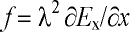
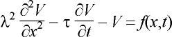 , (9)
, (9)
where l and t are the fibre’s length and time constants,
respectively; the coordinate x measures the distance along the axon.
The activating function, f, describes the sources of excitation; its
computation requires information about the coil and its location as well as
about the tissue surrounding the fibre. From Eq. 9, the axon is depolarised
where f is negative and hyperpolarised where it is positive.
Equation 9 holds as such for bent axons and in its compartmental form also
for myelinated and finite-length axons [111]. The axon dynamics, described by
the Hodgkin-Huxley model, can be included in the
cable equation [12,138], but the mathematical treatment becomes non-linear and
complicated. Provided that the electric field inside the axon can be assumed
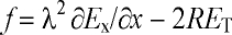
to be axial, the resulting activating function f in magnetic
stimulation is [138]:
 , (10)
where ¶ Ex/¶ x is the gradient of the component of E
along the axon; f is also known as Rattay’s activating function [131].
Fig. 4a illustrates that no activation occurs with a uniform field along the
axon, whereas Figs. 4b and 4c depict the gradient activation mechanism for
straight and bent axons.
Publications II and IV provide evidence that Eq. 10 is incomplete, since
also the field component transverse to the axon, ET, affects
V. The potential difference across the axon is of the order of
2RET, where R is the axon radius [81,137]. Thus, Eq.
10 must be changed accordingly, giving the modified activating
function:
 . (11)
The ratio of the transverse and gradient field mechanisms is independent of
the axon size. A schematic illustration of the axon membrane polarisation in a
transverse field is shown in Fig 4d.
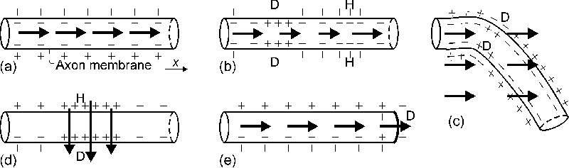
Figure 4. A schematic illustration of the activation
mechanisms. The axon membrane polarisation is sketched for different
externally applied electric field patterns (arrows): (a) uniform E
along the axon, no change from the resting state; (b) gradient activation,
with ¶ Ex/¶ x¹ 0; (c) bent axon in
uniform E, depicting only the gradient activation; (d) transverse
activation, with E locally across the axon; (e) axon terminating in
uniform E. D and H denote depolarisation and hyperpolarisation,
respectively. Although not illustrated, it is assumed that E is equal
outside and inside the cells.
3.2.2 Geometrical factors affecting the excitability
Neuronal excitability changes because of various geometrical factors,
e.g., axon terminals, bending, branching, nonuniformity and tapering
and volume-conductor nonuniformities [137]. Especially, bends and terminations
are thought to play a key role in TMS [90]. High effective ¶ Ex/¶ x
values are achieved at bends even in homogeneous E [1,63] (see, Fig.
4c). In thin curved axons, the relative contribution from the transverse field
ET (Eq. 11) is small as compared to ¶ Ex/¶
x.
Computer simulations [111] and in vitro experiments [110] suggest
that if the coil is placed close to the end of axon, or the axon is short
(<6–8 cm), the axon membrane is preferentially
depolarised at the end by the field component parallel to the axon. This is
illustrated in Fig. 4e for an axon terminating in a uniform field.
The cable equation (Eq. 9) applies for isolated axons, but in fibre bundles
the nearby axons may change the extracellular potential significantly. Both
the excitability and the locus of activation vary with the position of the
fibre in the bundle [108,109].
3.2.3 Strength-duration
relationship
The cell membrane behaves as a leaky integrator with a time constant of
about 150 ms, and hence the shorter the pulse, the
less energy is required for excitation [8,111,119]. On the other hand, the
minimum pulse intensity is achieved when the effective pulse duration is
greater than the chronaxie time of the neurone. Fig. 5 depicts the energy-duration and strength-duration
curves for TMS while holding the coil inductance and circuit resistance
constant and changing the capacitance. The efficiency is at maximum with brief
intense pulses, but this solution requires a low capacitance and a high
capacitor voltage. The maximal useful voltage is limited by the availability
and price of power electronics components.
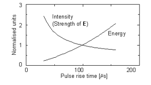
Figure. 5. Calculated normalised threshold capacitor energy
and peak value of E as function of zero-to-peak rise time. Values are
normalised to rise time of 100 ms. Circuit inductance
L = 20 mH and resistance
R = 50 mW. The capacitance
C ranged from 20 to 600 mF. Current shape was
biphasic and membrane time constant t = 150 ms.
Although not shown, the energy-duration curve levels
off at a constant value for very short pulses.
3.3 Locus of excitation
The locus and mechanisms of activation are of great consequence when
looking for the optimal shape of E to activate specific cortical
patches or when interpreting measurements. This section presents some relevant
experimental results separately for distal, spinal root and brain stimulation.
3.3.1 Distal nerve stimulation
Recalling the theory presented in chapter 3.2.1, there are two expected
mechanisms of activation in distal nerve stimulation: the gradient and
transverse field mechanisms. Experimentally, the site of activation has been
argued to be at the negative peak of ¶
Ex/¶ x [13,110,111,115,132,
133,138], but some reports display strong activation with coil orientations
that induce no ¶ Ex/¶ x along the nerve [34,57,78,89,117]. Publication
IV was aimed at addressing this discrepancy. For this purpose, the locus of
activation, determined from the latency of surface EMG responses, was mapped
with different coil placements. The modified activating function (Eq. 11),
which includes the contribution from both gradient and transverse fields, was
found to predict well the locus of activation. Thus, these results suggest
that there is no discrepancy, but that two separate mechanisms are responsible
for the membrane depolarisation.
Bones change notably the induced field distribution as well as the elicited
neuronal activation. For instance, Maccabee et al. [91] stimulated
sheep phrenic nerve in a saline container. Insertion of solid plastic
cylinders near the nerve caused preferential activation from points of the
nerve near the plastic. Something similar has been observed in facial nerve
stimulation, where the greatest excitability was at the exit from the temporal
bone [135].
3.3.2 Stimulation of the spine and spinal roots
The present magnetic stimulators are not powerful enough to stimulate
directly the descending spinal tracts [26,27], since the spinal bones
attenuate greatly the induced E (chapter 3.1.3). On the other hand,
spinal roots can be stimulated magnetically, but the response
latency does not change smoothly with coil position [26]. This is thought to
be because the roots are bent near the neural foramen, which serves as a
high-excitability
3.3.3 Brain stimulation
Characteristic dimensions of the shapes of cortical neurones are small
compared with the distances over which the induced electric field varies.
Hence, cortical neurones are likely to be activated at terminations (Fig. 4e)
or at axonal bends (Fig. 4c), where the effective gradient of E along
the axon can be great. Consequently, TMS activation most probably takes place
at the maximum of the externally applied E. The contribution of the
transverse activation mechanism is small since the axons are thin. On the
other hand, E can be maximal in low-conductivity regions, which could
help to determine the site of stimulation, but also complicates the study of
the activating mechanisms.
Comparative results from localisation of the somatosensory cortex with TMS
and other methods support that the activation occurs at the maximum of
E. Recently, Krings et al. [82,83] compared TMS maps with direct
cortical stimulation results, finding agreement to within less than 5-10 mm. The site of maximal E in TMS has been found
to agree with the localisation results from MEG
[103,104,146,Publication V] and PET [167] to within 10-20 mm. Similarly, fMRI, PET and TMS have localised the
frontal eye field to the precentral gyrus [22,127]. Despite the agreement
between results from TMS and functional imaging, different neuronal structures
may be involved.
Not only the strength, but also the direction of the induced E in
the brain affects the locus and strength of activation. The motor activation
is strongest when the cortical E in the contralateral precentral gyrus
is in the posterior-to-anterior direction. This possibly means that TMS of the
primary motor cortex preferentially activates elements in the posterior bank
of the precentral sulcus that are parallel to the induced field [121], or at
bends [90]. This is different from MEG, which reflects postsynaptic activity
[60]. Hence, although there is a reciprocity between the macroscopic field
theory for MEG and TMS, different cellular-level phenomena are involved.
TMS is thought to affect neurones in the cortex, rather than deep parts of
the corticospinal tract [101]. Corticospinal neurones are presumably activated
transsynaptically at low TMS intensities, since the response la-
tency to TMS is often 2 ms longer than to TCES [38,144], which
stimulates the corticospinal neurones directly. On the other hand, intense TMS
pulses often yield latencies similar to TCES, suggesting direct activation of
the corticospinal axons.
At cellular level, TMS is thought to excite axons rather than the cell body
or other parts of the neurones [88] since the measured chronaxie [8] and
intervals for facilitation [145] in peripheral motor axonal and brain
excitation are similar.
The mechanisms of repetitive TMS (rTMS) have not been examined so far. The
electromagnetic theory and the cable theory for single-pulse TMS remain
unchanged for rTMS. However, it is possible that at high repetition rates the
cellular-level effects of rTMS differ from those of single-pulse TMS.
4 Instrumentation
4.1 Available types of stimulators and
coils
There are two stimulator types: single-pulse devices and repetitive TMS
(rTMS) devices that generate trains of stimuli at 1-60 Hz. Commercial equipment are provided by three main
manufacturers: Cadwell Laboratories, Inc. (Kennewick, USA), Magstim Company,
Ltd. (Whitland, UK) and Medtronic Dantec NeuroMuscular (Skovlunde, Denmark).
Dantec and Magstim have add-on modules to their single-pulse devices that
can be used to drive one coil with two to four pulses separated by 1 ms to 1
s. These devices are called paired-pulse or quadruple-pulse stimulators. Two
stimulator units can be used together to drive separate coils to stimulate
different regions at the same time or in quick succession. This TMS mode is
called double-pulse TMS.
The rTMS devices operate at 10-60 Hz at 40–100% of
the maximum intensity of single pulses. The duration of sustained operation is
limited by coil heating to 100–1,000 pulses at maximum power. With proper coil
cooling, the duration of the stimulus train can be made unlimited. Cadwell
makes coils with continuous water cooling, whereas Magstim makes air-cooled
coils.
The current pulse properties vary among manufacturers. Three pulse
waveforms are available: i) monophasic, i.e., rapid rise from zero
to peak and slower decrease to zero; ii) biphasic, i.e., one damped
sine pulse; and iii) multiple-cycle damped sine pulse. The Dantec MagPro model
is equipped with a switch that allows selection between monophasic and
biphasic pulse shapes. Most of the Magstim devices use a monophasic pulse.
Cadwell devices generate a biphasic pulse, although earlier MES-10 units had a
multiple-cycle sine pulse. Rapid charging of the capacitors requires that the
rTMS devices use biphasic currents. The initial direction of the current in
the coil can be switched in some Dantec stimulators.
The current pulse duration is typically 200-300
ms for biphasic and about 600 ms for monophasic pulses. The peak current generated by the
commercial devices is 2-8 kA. Operating voltage of
TMS devices is typically 2-3 kV and the power
consumption 2–3 kW at maximum stimulus intensity.
The standard stimulating coils are either circular or 8-shaped. Some
Cadwell coils are drop-shaped with one rectangular edge
(Focalpoint™); the benefit from the shape is
questionable. Magstim sells 8-shaped cone coils with angled wings that fit the
head and Dantec has a similar circular cone coil. The cone coils are somewhat
more effective than planar ones, but at the cost of focality. The diameter of
the coils ranges from 50 to 150 mm. The coils are usually wound of 10–30
concentric turns of rectangular copper wire (gauge, e.g., 1×5
mm2), resulting in an inductance of 15-30
mH.
Prototype four-leaf coils have been presented with four coplanar wings
[140] suitable for peripheral stimulation. Another new idea is the so-called
half-toroid ("slinky") coil, which is wound with the turns in different angles
while maintaining the tangency along one edge [134,171].
The TMS equipment developed and used at the BioMag Laboratory has two
independent stimulator channels that are controlled by a computer. The maximum
stimulus repetition rate is 1 Hz at full intensity and the system
operates at 3 kV. The coils are 8-shaped and water-cooled and their outer
diameter ranges from 30 to 50 mm. The current pulse shape is biphasic
with rise time ranging between 70 and 100 ms
depending on the coil.
TABLE 1.
Definition and importance of main figures of
merit for the optimisation
and the evaluation of magnetic
stimulators
| Figure of merit |
Quantity to be
minimised |
Importance |
| Stimulator's efficacy |
Input power |
Stimulus repetition
rate |
| Coil's efficacy |
Peak magnetic energy |
Price, weight and size
of
components |
| Coil heating |
Temperature rise /
pulse |
Duration of pulse trains and
of sustained operation |
| Focality |
Area bound by the
half-
maximum of E |
Spatial
resolution |
4.2 About optimisation of the
stimulator
Publication VI addresses the optimisation of the TMS coil and the selection
of the power electronics components. The optimal design depends on the
application and how different qualities are weighted. Optimisation should
hence begin by selecting the quality criteria and the weighting rules for
computing the costs. The key task is to identify the members of three variable
categories:
· constraints, e.g., safety
regulations
· quantity/quantities to be minimised,
e.g., fabrication costs
· adjustable
parameters, e.g., coil dimensions.
The most important physical quantities that determine the quality of
magnetic stimulators are listed in Table 1; Publication VI gives the formulas
to calculate their values. Unfortunately, the quantities are competing,
e.g., focal coils have a lower efficacy than otherwise similar
coils.
As a rule, the coil is the main item to be optimised. Publication VI
focused on minimising the stimulator’s power consumption by changing the
coil’s winding structure and wire gauge. The procedure could improve
especially the efficacy of small coils by winding them into solenoids instead
of flat spirals. This procedure has been applied to design small water-cooled
coils for the TMS equipment at the BioMag Laboratory. In the literature, the
results of coil optimisation have remained of little use since
the definition of the "optimum" has been omitted [86,105,116]. In one
study, a mathematical method was used to maximise the focality by changing the
coil shape [141]. The resulting most focal coil shape was found to be roughly
8-shaped.
4.3 Coil construction and
fabrication
Coil design must always be taken into account when constructing TMS
equipment. Effective design is hindered by the high amount of energy that must
be driven through the coil in a very brief time. In brain stimulation this
energy is about 500 J, which would suffice to lift a weight of 1 kg to a
height of 50 m.
The intense submillisecond current pulses cause strong expanding and
compressing forces in the coil. The forces are even tens of kilonewtons and
thus the cross-sectional wire size must be large and the potting material
resistant. The forces are proportional to the peak energy in the coil.
Optimally, the coils are wound so that the forces are compressing in the
direction where the coil touches the head.
In rTMS, an additional trouble is that tens of W/Hz of power is dissipated
in the coil. The coil being usually placed against the head, according to the
safety standards its surface temperature must not exceed 41ºC. One should also
avoid high wire temperatures (100-120ºC), since these
deteriorate insulation, decreasing safety and the coil’s life time. Built-in
temperature sensors and effective cooling can be used to guard against
excessive temperatures.
Problems with power consumption and coil heating can be alleviated by
reducing the coil’s resistance, determined by the wire gauge and coil geometry
[Publication VI]. When the cross-sectional dimensions of the wire exceed 1 to
2 mm, the skin and proximity effects change the current distribution in the
wire [154], and may increase the direct current resistance significantly.
Striped, foil or litz wire can be used to reduce the skin and proximity
effects. The skin effect causes the current to flow mainly on the surface of
thick wire; hence, tubular wire can be used without affecting the resistance.
Liquid coolant can then flow inside the wire, as it is done in the BioMag
Laboratory’s TMS coils.
The voltage over the coil’s connectors may be 3 kV and depending on how the
coil is wound the voltage across adjacent turns can be from 200
to 1,000 V. The wire insulation (varnish, film, mylar paper) must have the
necessary dielectric strength and resist chemical solvents of the potting
material (epoxy resin, polyurethane foam). The electrical and liquid coolant
contacts must be tightly fastened and well insulated.
The intense current gives rise to a clicking sound from the coil, cables
and capacitor, exceeding 100 dB near the coil. To reduce the noise from the
coil, researchers at the BioMag Laboratory are investigating the possibility
to encapsulate the coil in vacuum or place a vacuum shield between the coil
and the subject [67].
4.4 Focality of stimulation
The capability to concentrate, or focus, the induced E to small
cortical patches deserves special attention since it limits the spatial
resolution of TMS. Focusing is possible in two dimensions only [61] (see
chapter 3.1.3).
A convenient measure of focality in TMS is the area of the spherical
surface bound by the half-maximum of E, listed in Table 2 for some
presently available commercial coils. Table 2 lists also the peak E
values obtained while driving the coils with
dI/dt = 108 A/s; in practice, the dI/dt
values vary among manufacturers. For comparison, the same values are given
for a hexagonal array of 19 circular coils, partially realised at the BioMag
Laboratory (chapter 5.2). The focality of the multichannel array is superior
due to the use of many coils that are smaller than normal [Publication
VII].
The 8-shaped coil is much more focal than the circular coil. In practice,
however, the circular coil is sometimes preferred over the 8-shaped coil
because motor responses can be promptly evoked without need for precise coil
positioning. The 8-shaped coil is chosen for better control of excitation. The
focality and the strength of stimulation depend on the coil size and on the
distance from the coil, both degrading quickly with increasing depth. For very
small radius the focality levels off at a constant value.
TABLE 2.
Characteristics of some coils. Circular coils
were placed edge-tangentially and
8-shaped coils tangential to the
scalp. The array coils pointed to the centre of the head.
The
computation was done on a 80-mm-radius spherical surface 20 mm below the
coils. The spherical model was used and dI / dt = 108
A/s.
| Manufacturer |
ID / OD
[mm] |
N
[turns] |
Focality
[cm2] |
Peak E
[V/m] |
| |
Circular coils |
|
|
| Cadwell a |
72 / 85 |
14 |
96 |
170 |
| Dantec b |
74 / 94 |
11 |
103 |
130 |
| Magstim (type 9762)
c |
40 / 94 |
15 |
96 |
130 |
| |
8-shaped coils |
|
|
| Cadwell a |
42 / 54 |
14 (×2) |
18 |
210 |
| Dantec (type B55)
b |
34 / 54 |
11 (×2) |
18 |
150 |
| Magstim (type 9790)
c |
56 / 87 |
9 (×2) |
33 |
180 |
| |
BioMag 19-coil arrays |
|
|
| BioMag 19 array |
OD 30 |
30 |
7 |
55. d |
| BioMag 19 array |
OD 40 |
30 |
12 |
105.
d |
ID = inner diameter; OD = outer diameter.
a
Approximate geometry from [143]; b from [115]; and c
from [73].
d Value when the sum of the absolute dI/dt
values in all coils is 108 A/s.
5 New advanced techniques
5.1 Computer-assisted TMS
In currently available commercial TMS systems the coil is positioned
manually above the head, the location of the coil being determined on the
basis of skull landmarks. Although TMS is used enthusiastically, users
strongly criticise the difficulties of focusing the activation in desired
targets. Because of the large coils and manual placement, the reproducibility
and repeatability are often poor.
Computer-assisted stereotactic TMS is under development at the HUCH BioMag
Laboratory. The essence of computer-assisted TMS is an intelligent
user-interface, by aid of which the operator may plan, perform, monitor and
document the experiments in a controlled and reproducible manner. An important
part of the software is the calculation of the electric field induced in the
brain. Stereotactic stimulus targeting is made possible by 3D localisation of
the coil/coils with respect to the head and by displaying the MR images on the
computer screen. The BioMag system is realised using a motorised coil holder
and frameless stereotaxy based on a 3D electromagnetic pointer. The concept of
computer-assisted TMS is illustrated in Fig. 6.
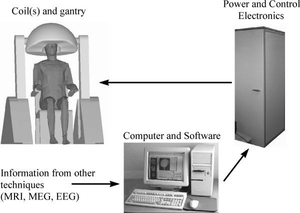
Figure 6. Computer-assisted TMS. System comprises gantry,
patient chair, computer, control and power electronics circuits and power
source. One or a few coils may be used, or an array of many coils.
Computer-assisted TMS enables new useful concepts for brain research.
Stereotactic targeting allows stimulation of a given location in the cortex or
a given anatomical structure. For instance, the functional organisation of the
brain can be studied with a greatly improved spatio-temporal resolution. The
stimulus may be modified both spatially and temporally
during tasks in order to identify the cortical areas that are necessary for
the task and the order in which they process the data.
In computer-assisted TMS, information from brain imaging techniques can be
used in planning the stimulation parameters as well as in the display and
interpretation of the results. In particular, digitisation of the coil
position on the MRI provides anatomical information of the stimulated location
[83,102], which enables stereotactic TMS, that is, precise stimulation of
selected anatomical locations. Stereotaxy allows selection of the stimulation
intensity level on the basis of calculating the actually induced electric
field in the target area instead of defining it as a percentage of the maximum
stimulator output or motor threshold. Frameless stereotaxy system and stimulus
targeting software have been realised in the BioMag Laboratory.
The merging of TMS with functional neuroimaging tools provides additional
benefits. The concurrent use of TMS with PET, fMRI and EEG has already been
demonstrated for the study of connectivity maps and the reactivity of the
stimulated cortex [18,127,Publication VIII]. Likewise, MEG can give the
location of specific cortical functional units in advance.
5.2 Multichannel TMS
Multichannel TMS [64], theoretically examined in Publication VII, refers to
the use of multiple independently controlled stimulating coils. It has a
number of advantages over stimulation with one coil, offering an alternative
solution for stereotactic TMS. One can stimulate multiple loci in one shot, or
with short delay between the pulses. The operator can also alleviate the
nuisance caused by the activation of undesired structures by suppressing the
field at selected locations. Moreover, it is possible to quickly scan brain
regions since the coils need not to be moved during scanning. The use of
multiple coils improves the mapping resolution since the stimulating field can
be made more concentrated. The shaping of the field can be effectively solved
using the MNE procedure described in Publication VII and chapter 3.1.2.
Publication VII analysed the properties of multichannel TMS; Fig. 7 shows
some of the results. Coil size is an important factor that determines the
focality and the power required to obtain a given stimulation intensity; the
number of coils is less important, yet significant. The focality depends
on the location of the target point with respect to the coils, being the
best below points where the coils touch each other. Multichannel TMS can
clearly improve the focality; with the present commercial single-coil devices
the focality is 10-15 cm2, while levels of
a few cm2 are attainable with multiple small coils. The focality is
improved at the cost of increased power consumption.
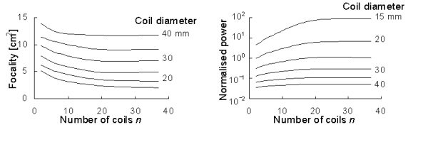
Figure 7. Left: Focality of cap-shaped array as
function of number of coils n. Coil diameter is between 15 and 40 mm.
Right: Normalised power required to induce a given peak value of
E. Adapted from Publication VII.
Multichannel TMS can also be used to produce sham stimulation by selecting
the coil currents so that the electric field induced in the brain is small,
but the subjective sensations due to scalp stimulation and coil click can be
predicted to be similar to real TMS [147].
The main drawback of multichannel TMS is that it is much more expensive
than computer-assisted stereotactic TMS with one coil. This is because the
power electronics design as well as the power source and mechanical
construction are more complicated.
5.3 TMS-compatible EEG
The brain’s electrical activity related with the TMS pulse can be detected
with EEG [2,32,84,97,151]. The EEG amplifiers are, however, prone to external
disturbance and in the studies cited the recording of the EEG to TMS has been
possible only using 2 to 3 electrodes located so that the disturbance from the
TMS pulse is little.
Publication VIII presents a TMS-compatible EEG system. The BioMag
high-resolution EEG system allows free positioning of all its 60 electrodes
[66].
The EEG is artefact-free in just a few ms after the stimulus pulse;
problems with the artefacts are dealt with sample-and-hold circuits that pin
the amplifier outputs at a constant level during the TMS pulse [158]. Scalp
burns resulting from the eddy current in the electrodes can be avoided using
low-conductivity materials. The electrodes are optimally small and have a cut
that interrupts the path of the eddy current [142].
Concurrent use of TMS and EEG has three basic uses. 1) EEG can be used to
locate the neuronal activity elicited by TMS, and its spread to other regions,
so as to determine reactivity and connectivity patterns. 2) One can study how
the brain processes information from the periphery by determining
temporo-spatially the effects of TMS on evoked and event-related potentials
(EPs and ERPs). 3) EEG can be used when TMS is applied as a treatment to
monitor for any abnormality, or to control on-line the efficacy of the
treatment. Many more applications will become feasible with better
understanding of the interaction of the TMS fields and the neurones, and of
the head as a volume conductor.
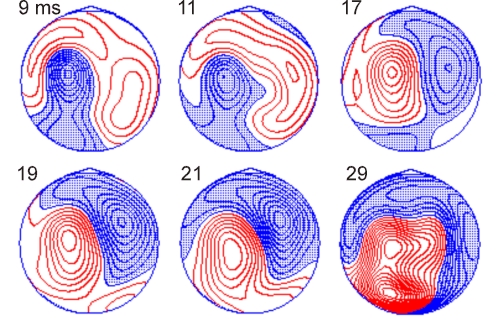
Figure 8. Contour maps of scalp potentials recorded with
60-channel EEG after left motor cortex TMS. Activity is drawn at selected
latencies between 9 and 29 ms post-stimulus time. The contour spacing is 0.4
mV; negative potentials are shaded. The
inter-stimulus interval was 2 s and 150 EEG responses to TMS at an intensity
slightly below motor threshold (90% MT) were averaged. In the drawings,
the head is seen from above, the nose pointing up.
Publication VIII displayed the distribution and spread of the TMS-
evoked EEG activity when the parietal or occipital lobe was stimulated.
Figure 8 shows the scalp potential distribution elicited by TMS over the left
hand-motor area from one healthy subject. As in Publication VIII, the early
activity is dominantly near the stimulated regions. After that, also the
opposite hemisphere becomes activated, indicating transcallosal signal
transmission. At later time points, not shown in Fig. 8, interpretation of the
activation patterns becomes complicated since many cortical regions are active
simultaneously and there will be also evoked potentials due to the activation
of the scalp and of the auditory pathways.
6 Safety
TMS has been used since 1985; today, thousands of stimulators are in use.
The present understanding is that single-pulse TMS is safe, if general
guidelines are respected. However, high-frequency rTMS may have undesired
effects (seizures, pain from muscle contraction, arm jerking, crying,
transient hemianopia). New guidelines for TMS and rTMS are needed since in the
last few years the number of pulses has risen from hundreds to thousands in
one examination [19].
6.1 Known adverse effects
Some immediate side effects to TMS are known. Seizure induction is the most
serious of them. Single-pulse TMS has produced seizures in patients
[28,47,62,75], but never in healthy subjects. In epileptic patients, there is
to date only one report of seizure definitely triggered by single-pulse TMS
[28]. Instead, rTMS at rates of several Hz has caused seizures even in
volunteers with no neurological problems or history of epilepsy
[24,99,123,165].
A frequent harmless, but uncomfortable, effect is a mild headache, which is
probably caused by the activation of scalp and neck muscles. The headache may
persist after the end of stimulation session and responds well to mild
analgesics.
TMS is accompanied by loud clicking sound from the coil that can exceed
100 dB near the coil [152]. Most sound energy is in the frequency range
2–7 kHz. The noise may exceed criteria limits for sensorineural hearing loss
[31].
It is assumed that harmful effects of TMS are related to the induced
electric field, since the body tissue is transparent to low-frequency magnetic
fields. Heating of the brain is of the order of 10-6 °C/pulse and unlikely to cause deleterious effects
[5]. Theoretical maximum power dissipation from rTMS in the whole brain is
about 3 mW/Hz [39]. Mild burns from scalp electrodes [123] can be avoided
using special-designed electrodes [142].
Many tests, including blood pressure, pulse rate, balance, gait and serum
prolactin and cortisol levels [71,123,166], have revealed no statistically
significant changes after TMS. The same is true for cognitive tests;
naturally, naming and verbal fluency tasks can be transiently disturbed by
TMS. Documented consistent changes include at least a lateralised effect on
immune functions (T-lymphocytes) [4] and changes in thyroid-stimulating
hormone levels after prefrontal stimulation [53].
Spontaneous EEG following TMS has been found to be normal. Izumi et
al. [69] reported slowing of the EEG at 150 ms post-TMS and other changes
lasting 400-600 ms, but these findings are not
necessarily relevant for the safety of TMS since similar changes are caused by
sensory stimuli. Generally, EEG is not a good test of safety since it is not
sensitive to mild or additive cellular dysfunction. However, monitoring of the
EEG during rTMS may be useful in order to stop the experiment if abnormalities
appear.
The few existing histopathological studies have not found any definite
TMS-related changes. In one study, rTMS (2,000 pulses at 20 Hz) was performed
in two patients who were assigned to temporal lobectomies because of medically
intractable epilepsy [48]. Histologic study of the surgical specimen did not
show any lesions attributable to TMS. Most animal models have failed to find
negative effects from TMS [169]. One study in rats reported microvacuolar
changes when using very high stimulus intensities [94]; these findings have
been criticised by other authors [163]. A study in the cat did not reveal any
acute adverse changes following TMS, assessed by cortical blood flow, blood
pressure and heart rate measurements [46].
6.2 Guidelines
Guidelines for safe TMS and rTMS have not been conclusively established.
The following text lists some general recommendations. For reviews, see Refs.
[136,163].
In the USA, clinical investigations for the FDA (Food and Drug
Administration) approval of TMS are underway, but prompt FDA approval is
unlike. According to the FDA, TMS at frequencies of ³
1 Hz always carries significant risk, whereas certain studies using lower
frequencies may not [163].
Protocols should exclude individuals with intracranial metallic or magnetic
objects. The magnetic field of the TMS coil will attract ferromagnetic objects
and repel nonmagnetic conductors. This force increases quickly with size and
conductivity of the object. TMS should never be administered in the vicinity
of any implanted electronic devices, since it may disturb their function.
The experimenter should take into account possible seizures when working
with single-pulse TMS in patients and always with rTMS. Already when designing
experiments, one should keep in mind the great medical and social impact that
a seizure may have on the subject’s well-being. Generally, spread of
excitation in the brain can lead to tonic-clonic seizures. For safe rTMS,
there is a tradeoff between the maximum stimulus intensity and the pulse rate:
it has been recommended that the excitability spread is avoided if at 100% of
motor threshold (MT) the pulse rate is below 10 Hz and at 150% MT below
1 Hz [123,163,166]. The duration of the inter-train interval and the
number of trains changes the safe limits, at least when the inter-train
interval is less than 5 s [24].
When stimulating non-motor areas, it is important to note that strong brain
activation can occur without subjective sensations or other observable
effects. It is more adequate to limit TMS on the basis of the calculated
electric field intensity and distribution. There is no experience of the
seizure threshold with widespread activation such as might be available with a
whole-scalp TMS array.
Hearing protection aids are recommended for both the examiner and the
patient, although safety regulations would allow 1,000–10,000 pulses daily
[152]. The new devices by Magstim Company are reasonably quiet, so that
hearing protection is normally unnecessary.
Since voltages of up to 4 kV can be present in the TMS equipment, the coil
must never be connected or disconnected before the capacitor is fully
discharged. The coils and cables should be regularly checked for visible
failures. The stimulator case must be opened by authorised persons only.
It is extremely important for the future of TMS/rTMS that the experimenters
document all harmful effects and the stimulation parameters that produced
them. If possible, rTMS experiments should be videotaped and the EEG recorded.
Good documentation is crucial for the updating of guidelines for safe
use.
7 Applications
Recording of motor-evoked potentials (MEPs) has made TMS a routine tool to
probe the conduction of the brain’s descending motor pathways. Interest in TMS
is now rapidly increasing also in the basic research: TMS has already been
used, e.g., to transiently suppress visual detection, halt speech,
induce verbal memory errors, impair learning, localise cerebral functions and
explore cortical excitability and intracortical connectivity.
This section briefly outlines selected clinical and therapeutic
applications as well as uses in basic brain research [25,40,114,160]. Magnetic
stimulation of the PNS is not considered here.
7.1 Clinical use
Since the first TMS studies the clinical focus has been on measuring the
excitability thresholds and motor conduction in patients with motor deficits.
TMS has revealed altered excitability thresholds and response latencies in
several clinical circumstances, including multiple sclerosis [7], motor
neurone disease [16] and cervical spondylosis [20]. TMS has provided new
significant information about many diseases, but, at least presently, the
diagnostic value of TMS is limited because it lacks sensitivity [56].
Since motor deficits are common in stroke and head and spinal injuries, TMS
may be used to acquire objective evidence as to the severity of pyramidal
tract damage [85,112]; this complements the anatomical evidence derived from
CT and MRI, and the clinical evidence based on the
acute impairment. It has been suggested that TMS responses would reflect
the prognosis of recovery from stroke, at an early stage [130].
TMS may provide a quick and inexpensive way of locating functionally
important cortical areas in patients assigned to brain surgery
[82,103,104,168]. Likewise, rTMS can be used to lateralise speech [74,164],
although the reliability has been called into question [99].
TMS shows promise in pharmaceutical research because TMS-related indices
can give additional evidence of the functional efficacy of medication, the
indices being, for instance, spatio-temporal changes in the cortical
reactivity and excitatory and inhibitory responses. In their pioneering study,
Ziemann et al. [170] observed consistent changes in specific TMS
responses when the type of epileptic medication was changed (GABAergic
vs. sodium channel-blocking drugs). Similarly,
Puri et al. [129] found accelerated TMS responses in untreated
schizophrenia, pointing up the potential additional value of TMS in
psychiatric disorders.
7.2 Basic brain research
In cognitive and behavioural sciences, TMS is used to turn off
non-invasively the function of specific cortical regions to produce
temporarily artificial lesions. This allows functional identification of areas
of the brain that are important for the given task. Earlier, such studies were
limited to animals or human individuals with pathology. In studies of how the
brain processes external input, TMS may be used to impair performance by
disturbing relevant signals, but also to improve performance by disturbing
irrelevant and competing signals [161].
Pioneering studies have used TMS to study, for instance, the encoding of
objects and space in memory [107], visual pathways [3,14,100], speech
[33,156], and callosal connections [32,98]. Plasticity of the cortical
topography has been studied with TMS in patients suffering from stroke [21,58]
or amputations [76] as well as in normal volunteers. Using rTMS, it was
recently shown that the visual cortex in the blind processes functionally
relevant information [30]. Also, rTMS has been used to show plasticity of the
finger representation area during learning of a finger tapping task
[122].
7.3 Therapeutic use
A recent revolutionary finding is that rTMS may have therapeutic potential
in patients with medication-resistant depression. George et al. [52]
reported robust benefit in 2 and slight benefit in 2 of 6 patients;
Pascual-Leone et al. [124] found remarkable benefit in 11 of 17
patients lasting at least some weeks. Other studies have reproduced the
effects [51,77]. In the depression therapy trials some 1,000 pulses of 10-Hz
rTMS have been administered daily to the left dorsolateral prefrontal cortex
for several consecutive days. Interestingly, in healthy subjects rTMS to left
prefrontal areas appears to have an opposite effect, triggering crying
[99,120].
Despite promising results, the efficacy of rTMS in depression treatment has
so far not been clinically proven. The debate on how to affirmatively assess
its efficacy is underway. However, rTMS may challenge electro-convulsive
therapy (ECT) [77].
Treatment with TMS has been studied also in several psychiatric disorders,
including schizophrenia [50] and obsessive-compulsive disorder [55].
Therapeutic applications may evolve also in the neurological field. Repetitive
TMS may speed up movements [125] and reset tremor [126] in Parkinson’s disease
and reduce spasticity in multiple sclerosis [113]. Moreover, it has been
speculated that rTMS at 1 Hz could have a normalising effect on excitability
threshold in epileptogenic regions [166].
8 Summary
Transcranial magnetic stimulation (TMS) refers to excitation of the human
brain by means of electromagnetic induction, allowing one to interfere
non-invasively with the function of the cerebral cortex. TMS is
well-established in the investigation of many neurological conditions that
affect the motor pathways. In addition, TMS shows great promise in basic brain
research, creating transient functional lesions in healthy volunteers.
Moreover, various therapeutic applications are presently evolving that employ
trains of TMS pulses.
In this thesis, models of the central physical and engineering aspects
underlying TMS were developed. Two principal realms were studied. First, the
calculation of the macroscopic electromagnetic fields due to
TMS was explored. Publications I and II derived a model that describes the
macroscopic fields in cylinder-shaped volume conductors, whereas Publication
III investigated the spherical head model. Second, the neuronal responses
resulting from the macroscopic field were considered. Publication IV compared
the theory with experimental results from peripheral nerve stimulation,
providing new direct evidence of how and where the neurones are activated.
Publication V compared the locating of the sensorimotor cortex with TMS and
MEG, finding a fairly good agreement, which information provides invaluable
evidence of the locus of TMS activation and suggests that TMS can be used in
locating the motor cortex.
As a second major effort of the thesis, models were used as a starting
point towards more effective TMS instrumentation. Publication VI presented a
procedure to optimise stimulator coils, the results indicating that the
presently available coils are far from being optimal. Publication VII derived
the mathematical theory for the effective use of multiple TMS coils, advantage
of which is improved targeting and focusing of stimulation. Publication VIII
demonstrated the feasibility of concurrent use of TMS and EEG, one of the
applications being the mapping of functional connections in the brain.
In conclusion, sound physical theories are the cornerstone of any
significant progress in TMS instrumentation. For instance, while frameless
stereotaxy is gradually becoming the standard way of locating the TMS coil
with respect to anatomical structures, precise targeting of the stimulation to
predefined cortical loci is not possible without modelling the actually
realised electromagnetic fields. Important advances also come along with the
merging of TMS with other neuroimaging tools. In fact, combined use of
different methods is a shared trend in brain imaging and in clinical
neuroscience.
List of
references
[1] Abdeen MA and Stuchly MA. Modeling of magnetic field
stimulation of bent neurons. IEEE Trans Biomed Eng. 41,
1092-1095. 1994.
[2] Amassian VE, Cracco RQ, Maccabee PJ and Cracco JB.
Cerebello-frontal cortical projections in humans studied with the magnetic
coil. Electroenceph clin Neurophysiol. 85, 265-272. 1992.
[3] Amassian VE, Cracco RQ, Maccabee PJ, Cracco JB, Rudell A
and Eberle L. Suppression of visual perception by magnetic coil stimulation of
human occipital cortex. Electroenceph clin Neurophysiol. 74,
458-462. 1989.
[4] Amassian VE, Henry K, Durkin H, Chice S, Cracco JB,
Somasundaram M, Hassan N, Cracco RQ, Maccabee PJ and Eberle L. Human immune
functions are differentially affected by left-sided versus right-sided magnetic
stimulation of temporo-parieto-occipital cortex. Neurology. 44
(Suppl 2), A133. 1994.
[5] Barker AT. An introduction to the basic principles of
magnetic nerve stimulation. J Clin Neurophysiol. 8, 26-37. 1991.
[6] Barker AT, Freeston IL, Jalinous R and Jarratt JA. Clinical
evaluation of conduction time measurements in central motor pathways using
magnetic stimulation of the human brain. Lancet. 1, 1325-1326. 1986.
[7] Barker AT, Freeston IL, Jalinous R and Jarratt JA. Magnetic
stimulation of the human brain and peripheral nervous system: an introduction
and the results of an initial clinical evaluation. Neurosurgery.
20, 100-109. 1987.
[8] Barker AT, Garnham CW and Freeston IL. Magnetic nerve
stimulation: the effect of waveform on efficiency, determination of neural
membrane time constants and the measurement of stimulator output. In Levy
WJ, Cracco RQ, Barker AT and Rothwell JC. Editors. Magnetic Motor
Stimulation: Basic Principles and Clinical Experience. Amsterdam: Elsevier
Science. 227-237. 1991.
[9] Barker AT, Jalinous R and Freeston I. Non-invasive magnetic
stimulation of the human motor cortex. Lancet. 1, 1106-1107. 1985.
[10] Barlow HB, Kohn HL and Walsh EG. Visual sensations aroused
by magnetic fields. Am J Physiol. 148, 372-375. 1947.
[11] Bartholow R. Experimental investigations into the
functions of the human brain. Am J Med Sci. 67, 305-313. 1874.
[12] Basser PJ and Roth BJ. Stimulation of myelinated nerve
axon by electromagnetic induction. Med Biol Eng Comput. 29,
261-268. 1991.
[13] Basser PJ, Wijesinghe R and Roth BJ. The activating
function for magnetic stimulation derived from a three-dimensional volume
conductor model. IEEE Trans Biomed Eng. 39, 1207-1210. 1992.
[14] Beckers G and Zeki S. The consequences of inactivating
areas V1 and V5 on visual motion perception. Brain. 118,
49-60. 1995.
[15] Beer B. Über das Auftrafen einer objective
Lichtempfindung in magnetischen Felde. Klin Wochenschr. 15,
108-109. 1902.
[16] Berardelli A, Inghilleri M, Cruccu G, Mercuri B and
Manfredi M. Electrical and magnetic transcranial stimulation in patients with
corticospinal damage due to stroke or motor neurone disease. Electroenceph
clin Neurophysiol. 81, 389-396.
1991.
[17] Bickford RG and Fremming BD. Neural stimulation by pulsed
magnetic fields in animals and man. 6th Int Conf Med Electr Biol Eng.
Tokyo. Abstract 7-6. 1965.
[18] Bohning DE, Shastri A, Nahas Z, Lorberbaum JP, Andersen
SW, Dannels WR, Haxthausen EU, Vincent DJ and George MS. Echoplanar BOLD fMRI of
brain activation induced by concurrent transcranial magnetic stimulation.
Invest Radiol. 33, 336-340.
1998.
[19] Brown P. Shocking safety concerns. Lancet.
348, 959. 1996.
[20] Brunholzl C and Claus D. Central motor conduction time to
upper and lower limbs in cervical cord lesions. Arch Neurol. 51,
245-249. 1994.
[21] Caramia MD, Iani C and Bernardi G. Cerebral plasticity
after stroke as revealed by ipsilateral responses to magnetic stimulation.
Neuroreport. 7, 1756-1760.
1996.
[22] Carter N and Zee DS. The anatomical localization of
saccades using functional imaging studies and transcranial magnetic
stimulation. Curr Opin Neurol. 10, 10-17. 1997.
[23] Cerri G, De Leo R, Moglie F and Schiavoni A. An accurate
3-D model for magnetic stimulation of the brain cortex. J Med Eng
Technol. 19, 7-16. 1995.
[24] Chen R, Gerloff C, Classen J, Wassermann EM, Hallett M and
Cohen LG. Safety of different inter-train intervals for repetitive transcranial
magnetic stimulation and recommendations for safe ranges of stimulation
parameters. Electroenceph clin Neurophysiol. 105, 415-421. 1997.
[25] Chokroverty S. Magnetic Stimulation in Clinical
Neurophysiology. Boston: Butterworth. 1990.
[26] Chokroverty S, Deutsch A, Guha C, Gonzalez A, Kwan P,
Burger R and Goldberg J. Thoracic spinal nerve and root conduction: a magnetic
stimulation study. Muscle Nerve. 18, 987-991. 1995.
[27] Chokroverty S, Flynn D, Picone M, Chokroverty M and Belsh
J. Magnetic coil stimulation of the human lumbosacral vertebral column: site of
stimulation and clinical applications. Electroenceph clin
Neurophysiol. 89, 54-60.
1993.
[28] Classen J, Witte OW, Schlaug G, Seitz RJ, Holthausen H and
Benecke R. Epileptic seizures triggered directly by focal transcranial magnetic
stimulation. Electroenceph clin Neurophysiol. 94, 19-25. 1995.
[29] Cohen D and Cuffin BN. Developing a more focal magnetic
stimulator. Part I: some basic principles. J Clin Neurophysiol. 8,
102-111. 1991.
[30] Cohen LG, Celnik P, Pascual-Leone A, Corwell B, Faiz L,
Dambrosia J, Honda M, Sadato N, Gerloff C, Catalá MD and Hallett M. Functional
relevance of cross-modal plasticity in blind humans. Nature. 389,
180-183. 1997.
[31] Counter SA, Borg E and Olofsson A. Oto-traumatic effects
of computer simulated magnetic coil impulse noise: analysis of mechanisms.
Acta Oto-Laryngol. 113, 699-705.
1993.
[32] Cracco RQ, Amassian VE, Maccabee PJ and Cracco JB.
Comparison of human transcallosal responses evoked by magnetic coil and
electrical stimulation. Electroenceph clin Neurophysiol. 74,
417-424. 1989.
[33] Cracco RQ, Amassian VE, Maccabee PJ and Cracco JB. Flow of
symbolic visual information from retina to vocalization. 6th Symp on Clinical
Use of Magnetic Stimulation. Kyoto, Japan. 28-30. 1995.
[34] Cros D, Day TJ and Shahani BT. Spatial dispersion of
magnetic stimulation in peripheral nerves. Muscle Nerve. 13,
1076-1082. 1990.
[35] Cuffin BN and Cohen D. Magnetic fields of a dipole in
special volume conductor shapes. IEEE Trans Biomed Eng. 24,
372-381. 1977.
[36] d'Arsonval A. Dispositifs pour la mesure des courants
alternatifs de toutes fréquences. C R Soc Biol. (Paris). 3,
450-457. 1896.
[37] D'Inzeo G, Esselle KP, Pisa S and Stuchly MA. Comparison
of homogeneous and heterogeneous tissue models for coil optimization in neural
stimulation. Radio Sci. 30, 245-253. 1995.
[38] Day BL, Thompson PD, Dick JP, Nakashima K and Marsden CD.
Different sites of action of electrical and magnetic stimulation of the human
brain. Neurosci Lett. 75, 101-106.
1987.
[39] De Leo R, Cerri G, Balducci G, Moglie F, Scarpino O and
Guidi M. Computer modelling of brain cortex excitation by magnetic field
pulses. J Med Eng Technol. 16, 149-156. 1992.
[40] Devinsky O. Electrical and magnetic stimulation of the
central nervous system. Historical overview. Adv Neurol. 63,
1-16. 1993.
[41] Dunlap K. Visual sensations from the alternating magnetic
field. Science. 33, 68-71.
1911.
[42] Durand D, Ferguson S and Dalbasti T. Effect of surface
boundary charge on neuronal magnetic stimulation. IEEE Trans Biomed
Eng. 39, 58-64. 1992.
[43] Eaton H. Electric field induced in a spherical volume
conductor from arbitrary coils: application to magnetic stimulation and MEG.
Med Biol Eng Comput. 30, 433-440.
1992.
[44] Esselle KP and Stuchly MA. Quasi-static electric field in
a cylindrical volume conductor induced by external coils. IEEE Trans Biomed
Eng. 41, 151-158. 1994.
[45] Esselle KP and Stuchly MA. Cylindrical tissue model for
magnetic field stimulation of neurons: effects of coil geometry. IEEE Trans
Biomed Eng. 42, 934-941.
1995.
[46] Eyre J, Flecknell P, Kenyon B, Koh T and Miller S. Acute
effects of electromagnetic stimulation of the brain on cortical activity,
cortical blood flow, blood pressure and heart rate in the cat: an evaluation of
safety. J Neurol Neurosurg Psychiatry. 53, 507-513. 1990.
[47] Fauth C, Meyer BU, Prosiegel M, Zihl J and Conrad B.
Seizure induction and magnetic stimulation after stroke. Lancet.
339, 362. 1992.
[48] Gates JR, Dhuna A and Pascual-Leone A. Lack of
pathological changes in human temporal lobe after transcranial magnetic
stimulation. Epilepsia. 33, 504-508. 1992.
[49] Geddes LA. History of magnetic stimulation of the nervous
system. J Clin Neurophysiol. 8, 3-9. 1991.
[50] Geller V, Grisaru N, Abarbanel JM, Lemberg T and Belmaker
RH. Slow magnetic stimulation of prefrontal cortex in depression and
schizophrenia. Prog Neuro-Psychopharm & Biol Psychiatry. 21,
105-110. 1997.
[51] George MS, Wassermann EM, Kimbrell TA, Little JT, Williams
WE, Danielson AL, Greenberg BD, Hallett M and Post RM. Mood improvement
following daily left prefrontal repetitive transcranial magnetic stimulation in
patients with depression: a placebo-controlled crossover trial. Am J
Psychiatry. 154, 1752-1756.
1997.
[52] George MS, Wassermann EM, Williams WA, Callahan A, Ketter
TA, Basser P, Hallett M and Post RM. Daily repetitive transcranial magnetic
stimulation (rTMS) improves mood in depression. Neuroreport. 6,
1853-1856. 1995.
[53] George MS, Wassermann EM, Williams WA, Steppel J,
Pascual-Leone A, Basser P, Hallett M and Post RM. Changes in mood and hormone
levels after rapid-rate transcranial magnetic stimulation (rTMS) of the
prefrontal cortex. J Neurophychol Clin Neurosci. 8, 172-180. 1996.
[54] Grandori F and Ravazzani P. Magnetic stimulation of the
motor cortex—theoretical considerations. IEEE Trans Biomed Eng.
38, 180-191. 1991.
[55] Greenberg BD, George MS, Martin JD, Benjamin J, Schlaepfer
TE, Altemus M, Wassermann EM, Post RM and Murphy D. Effect of prefrontal
repetitive transcranial magnetic stimulation in obsessive-compulsive disorder: a
preliminary study. Am J Psychiatry. 154, 867-869. 1997.
[56] Hallett M. Transcranial magnetic stimulation: a useful
tool for clinical neurophysiology. Ann Neurol. 40, 344-345. 1996.
[57] Hallett M, Cohen LG, Nilsson J and Panizza M. Differences
between electrical and magnetic stimulation of human peripheral nerve and motor
cortex. In Chokroverty S. Editors. Magnetic Stimulation in Clinical
Neurophysiology. Stoneham, MA: Butterworth. 275-287. 1990.
[58] Hamdy S, Aziz Q, Rothwell JC, Singh KD, Barlow J, Hughes
DG, Tallis RC and Thompson DG. The cortical topography of human swallowing
musculature in health and disease. Nature Med. 2, 1217-1224. 1996.
[59] Hämäläinen M and Sarvas J. Realistic conductivity geometry
model of the human head for interpretation of neuromagnetic data. IEEE Trans
Biomed Eng. 26, 165-171.
1989.
[60] Hämäläinen MS and Ilmoniemi RJ. Interpreting magnetic
fields of the brain: minimum norm estimates. Med Biol Eng Comput.
32, 35-42. 1994.
[61] Heller L and van Hulsteyn DB. Brain stimulation using
electromagnetic sources: theoretical aspects. Biophys J. 129-138. 1992.
[62] Hömberg V and Netz J. Generalised seizures induced by
transcranial magnetic stimulation of motor cortex. Lancet. 2,
1223. 1989.
[63] Hyodo A and Ueno S. Nerve excitation model for localized
magnetic stimulation of finite neuronal structures. IEEE Trans Magn.
32, 5112-5114. 1996.
[64] Ilmoniemi RJ and Grandori F. Device for applying a
programmable excitation electric field to a target. Patent FI/100458
(issued 15.12.1997), patent pending EP/94203134. Filed 13.10.1993.
[65] Ilmoniemi RJ, Hämäläinen MS and Knuutila J. The forward
and inverse problems in the spherical model. In Weinberg H, Stroink G and
Katila T. Editors. Biomagnetism, Applications and Theory. New York:
Pergamon Press. 278-282. 1985.
[66] Ilmoniemi RJ, Karhu J, Ruohonen J and Virtanen J. Method
and apparatus for mapping cortical connections. Patent pending
FI/964387 and PCT/FI97/00664. Filed 30.10.1996.
[67] Ilmoniemi RJ, Ruohonen J, Kamppuri J and Virtanen J.
Stimulator head and method for attenuating noise from the stimulating coil.
Patent pending FI/974371. Filed 28.11.1997.
[68] Irwin DD, Rush S, Evering R, Lepeschkin D, Montgomery B
and Weggel R. Stimulation of cardiac muscle by a time-varying magnetic field.
IEEE Trans Magn. 6, 321-322.
1970.
[69] Izumi S, Takase M, Arita M, Masakado Y, Kimura A and Chino
N. Transcranial magnetic stimulation-induced changes in EEG and responses
recorded from the scalp of healthy humans. Electroenceph clin
Neurophysiol. 103, 319-322.
1997.
[70] Jackson JD. Classical Electrodynamics. New York:
John Wiley & Sons. 1975.
[71] Jahanshahi M, Ridding MC, Limousin P, Profice P, Fogel W,
Dressler D, Fuller R, Brown RG, Brown P and Rothwell JC. Rapid rate transcranial
magnetic stimulation—a safety study. Electroenceph clin Neurophysiol.
105, 422-429. 1997.
[72] Jalinous R. Technical and practical aspects of magnetic
stimulation. J Clin Neurophysiol. 8, 10-25. 1991.
[73] Jalinous R. Guide to Magnetic Stimulation. Magstim
Company Ltd. 1997.
[74] Jennum P, Friberg L, Fuglsang-Frederiksen A and Dam M. Speech localization using
repetitive transcranial magnetic stimulation. Neurology. 44,
269-273. 1994.
[75] Kandler R. Safety of transcranial magnetic stimulation.
Lancet. 335, 469-470.
1990.
[76] Kew JJM, Ridding MC, Rothwell JC, Passingham RE, Leigh PN,
Sooriakumaran S, Frackowiak RSJ and Brooks DJ. Reorganization of cortical blood
flow and transcranial magnetic stimulation maps in human subjects after upper
limb amputation. J Neurophysiol. 72, 2517-2524. 1994.
[77] Kirkcaldie M, Pridmore S and Reid P. Bridging the skull:
electroconvulsive therapy (ECT) and repetitive transcranial magnetic stimulation
(rTMS) in psychiatry. Convulsive Ther. 13, 83-91. 1997.
[78] Kobayashi M, Ueno S and Kurakawa T. Importance of soft
tissue inhomogeneity in magnetic peripheral nerve stimulation. Electroenceph
clin Neurophysiol. 105, 406-413.
1997.
[79] Kolin A, Brill NQ and Broberg PJ. Stimulation of irritable
tissues by means of an alternating magnetic field. Proc Soc Exp Biol
Med. 102, 251-253. 1959.
[80] Kong JA. Theory of Electromagnetic Waves. New York:
John Wiley & Sons. 1975.
[81] Krassowska W and Neu JC. Response of a single cell to an
external electric field. Biophys J. 66, 1768-1776. 1994.
[82] Krings T, Buchbinder BR, Butler W, Chiappa KH, Jiang HJ,
Rosen BR and Cosgrove GR. Stereotactic transcranial magnetic stimulation:
correlation with direct electrical cortical stimulation. Neurosurgery.
41, 1319-1326. 1997.
[83] Krings T, Naujokat C and Graf v Keyrserlink D.
Representation of cortical motor function as revealed by stereotactic
transcranial magnetic stimulation. Electroenceph clin Neurophysiol.
109, 85-93. 1998.
[84] Kujirai T, Sato M, Rothwell JC and Cohen LG. The effect of
transcranial magnetic stimulation on median nerve somatosensory evoked
potentials. Electroenceph clin Neurophysiol. 89, 227-234. 1993.
[85] Lewko JP, Tarkka IM and Dimitrijevic MR.
Neurophysiological assessment of the motor and sensory spinal pathways in
chronic spinal cord injury. Restor Neurol Neurosci. 7, 225-234. 1995.
[86] Liu JL and Faust U. Analysis of coil parameters for
magnetic stimulation. Techn Health Care. 2, 43-52. 1994.
[87] Maass J and Asa M. Contactless nerve stimulation and
signal detection by inductive transducer. IEEE Trans Magn. 6,
322-326. 1970.
[88] Maccabee PJ, Amassian VE, Cracco RQ and Eberle LP.
Mechanisms of neuromagnetic stimulation of peripheral nerve. In Nilsson
J, Panizza M and Grandori F. Editors. Advances in Magnetic Stimulation:
Mathematical Modeling and Clinical Applications. Pavia, Italy: Salvatore
Maugeri Foundation. 117-128.
1996.
[89] Maccabee PJ, Amassian VE, Cracco RQ, Eberle LP and Rudell
AP. Mechanisms of peripheral nervous system stimulation using the magnetic
coil. Electroenceph clin Neurophysiol Suppl. 43, 344-361. 1991.
[90] Maccabee PJ, Amassian VE, Eberle L and Cracco RQ. Magnetic
coil stimulation of straight and bent amphibian and mammalian peripheral nerves
in vitro: locus of excitation. J Physiol. 460, 201-219. 1993.
[91] Maccabee PJ, Amassian VE, Eberle L, Rudell A, Cracco RQ,
Lai K and Somasundaram M. Measurement of the electric field induced into
inhomogeneous conductors by magnetic coils: application to human spinal
neurogeometry. Electroenceph clin Neurophysiol. 81, 224-237. 1991.
[92] Magnusson CE and Stevens HC. Visual sensations created by
a magnetic field. Am J Physiol. 29, 124-136. 1911.
[93] Mathis J, Seemann U, Weyh T, Jakob C and Struppler A. The
boundary effect in magnetic stimulation. Analysis at the peripheral nerve.
Electroenceph clin Neurophysiol. 97, 238-245. 1995.
[94] Matsumiya Y, Yamamoto T, Yarita M, Miyauchi S and Kling
JW. Physical and physiological specification of magnetic pulse stimuli that
produce cortical damage in rats. J Clin Neurophysiol. 9,
278-287. 1992.
[95] McNeal DR. Analysis of a model for excitation of
myelinated nerve. IEEE Trans Biomed Eng. 23, 329-337. 1976.
[96] Merton PA and Morton HB. Stimulation of the cerebral
cortex in the intact human subject. Nature. 285, 227.
1980.
[97] Meyer BU and Röricht S. Scalp potentials recorded over the
sensorimotor region following magnetic stimulation over the cerebellum in man:
considerations about the activated structures and their potential diagnostic
use. J Neurol. 242, 109-112.
1995.
[98] Meyer BU, Röricht S and Woiciechowsky C. Topography of
fibers in the human corpus callosum mediating interhemispheric inhibition
between the motor cortices. Ann Neurol. 43, 360-369. 1998.
[99] Michelucci R, Valzania F, Passarelli D, Santangelo M,
Rizzi R, Buzzi AM, Tempestini A and Tassinari CA. Rapid-rate transcranial
magnetic stimulation and hemispheric language dominance: usefulness and safety
in epilepsy. Neurology. 44, 1697-1700. 1994.
[100] Miller MB, Fendrich R, Eliassen JC, Demirel S and
Gazzaniga MS. Transcranial magnetic stimulation: delays in visual suppression
due to luminance changes. Neuroreport. 7, 1740-1744. 1996.
[101] Mills KR. Magnetic brain stimulation: a tool to explore
the action of the motor cortex on single human spinal motoneurons. Trends
Neurosci. 14, 401-405.
1991.
[102] Miranda PC, de Carvalho M, Conceicao I, Sales Luis ML and
Ducla-Soares E. A new method for reproducible coil positioning in transcranial
magnetic stimulation mapping. Electroenceph clin Neurophysiol.
105, 116-123. 1997.
[103] Morioka T, Mizushima A, Yamamoto T, Tobimatsu S,
Matsumoto S, Hasuo K, Fujii K and Fukui M. Functional mapping of the
sensorimotor cortex: combined use of magnetoencephalography, functional MRI, and
motor evoked potentials. Neuroradiol. 37, 526-530. 1995.
[104] Morioka T, Yamamoto T, Mizushima A, Tombimatsu S, Shigeto
H, Hasuo K, Nishio S, Fujii K and Fukui M. Comparison of magnetoencephalography,
functional MRI, and motor evoked potentials in the localization of the
sensory-motor cortex. Neurol Res. 17, 361-367. 1995.
[105] Mouchawar GA, Nyenhuis JA, Bourland JD and Geddes LA.
Guidelines for energy-efficient coils: coils designed for magnetic stimulation
of the heart. Electroenceph clin Neurophysiol Suppl. 43,
255-267. 1991.
[106] Mouchawar GA, Nyenhuis JA, Bourland JD, Geddes LA,
Schaefer DJ and Riehl ME. Magnetic stimulation of excitable tissue: calculation
of induced eddy-currents with a three-dimensional finite-element model. IEEE
Trans Magn. 29, 3355-3357.
1993.
[107] Muri RM, Rivaud S, Vermersch AI, Leger JM and
Pierrot-Deseilligny C. Effects of transcranial magnetic stimulation over the
region of the supplementary motor area during sequences of memory-guided
saccades. Exp Brain Res. 104, 163-166. 1995.
[108] Nagarajan SS and Durand DM. Analysis of magnetic
stimulation of a concentric axon in a nerve bundle. IEEE Trans Biomed
Eng. 42, 926-933. 1995.
[109] Nagarajan SS and Durand DM. A generalized cable equation
for magnetic stimulation of axons. IEEE Trans Biomed Eng. 43,
304-312. 1996.
[110] Nagarajan SS, Durand DM and Hsuing-Hsu K. Mapping
location of excitation during magnetic stimulation: effects of coil position.
Ann Biomed Eng. 25, 112-125.
1997.
[111] Nagarajan SS, Durand DM and Warman EN. Effects of induced
electric fields on finite neuronal structures: a simulation study. IEEE Trans
Biomed Eng. 40, 1175-1188.
1993.
[112] Netz J, Lammers T and Hömberg V. Reorganization of motor
output in the non-affected hemisphere after stroke. Brain. 120,
1579-1586. 1997.
[113] Nielsen JF, Klemar B, Hansen HJ and Sinkjaer T. A new
treatment of spasticity with repetitive magnetic stimulation in multiple
sclerosis. J Neurol Neurosurg Psychiatry. 58, 254-255. 1995.
[114] Nilsson J, Panizza M and Grandori F. Advances in
Magnetic Stimulation: Mathematical Modeling and Clinical Applications.
Pavia, Italy: Salvatore Maugeri Foundation. 1996.
[115] Nilsson J, Panizza M, Roth BJ, Basser PJ, Cohen LG,
Caruso G and Hallett M. Determining the site of stimulation during magnetic
stimulation of a peripheral nerve. Electroenceph clin Neurophysiol.
85, 253-264. 1992.
[116] Nyenhuis JA, Mouchawar GA, Bourland JD and Geddes LA.
Energy considerations in the magnetic (eddy-current) stimulation of tissues.
IEEE Trans Magn. 27, 680-687.
1991.
[117] Olney RK, So YT, Goodin DS and Aminoff JA. A comparison
of magnetic and electrical stimulation of peripheral nerves. Muscle
Nerve. 13, 957-963. 1990.
[118] Öberg PÅ. Magnetic stimulation of nerve tissue. Med
Biol Eng Comput. 11, 55-64.
1973.
[119] Panizza M, Nilsson J, Roth BJ, Grill SE, Demirci M and
Hallett M. Differences between the time constant of sensory and motor peripheral
nerve fibres: further studies and considerations. Muscle Nerve.
21, 48-54. 1998.
[120] Pascual-Leone A, Catalá MD and Pascual-Leone Pascual A.
Lateralized effect of rapid-rate transcranial magnetic stimulation of the
prefrontal cortex on mood. Neurology. 46, 499-502. 1996.
[121] Pascual-Leone A, Cohen LG, Brasil-Neto JP and Hallett M.
Non-invasive differentiation of motor cortical representation of hand muscles by
mapping of optimal current directions. Electroenceph clin
Neurophysiol. 93, 42-48.
1994.
[122] Pascual-Leone A, Grafman J and Hallett M. Modulation of
cortical motor output maps during development of implicit and explicit
knowledge. Science. 263, 1287-1289. 1994.
[123] Pascual-Leone A, Houser CM, Reese K, Shotland LI, Grafman
J, Sato S, Valls-Solé J, Brasil-Neto JP, Wassermann EM, Cohen LG and Hallett M.
Safety of rapid-rate transcranial magnetic stimulation in normal volunteers.
Electroenceph clin Neurophysiol. 89, 120-130. 1993.
[124] Pascual-Leone A, Rubio B, Pallardo F and Catalá MD.
Rapid-rate transcranial magnetic stimulation of left dorsolateral prefrontal
cortex in drug-resistant depression. Lancet. 348, 233-237. 1996.
[125] Pascual-Leone A, Valls-Solé J, Brasil-Neto JP, Cohen LG
and Hallett M. Akinesia in Parkinson's disease. I. Shortening of simple reaction
time with focal, single-pulse transcranial magnetic stimulation.
Neurology. 44, 884-891.
1994.
[126] Pascual-Leone A, Valls-Solé J, Toro C, Wassermann EM and
Hallett M. Resetting of essential tremor and postural tremor in Parkinson's
disease with transcranial magnetic stimulation. Muscle Nerve. 17,
800-807. 1994.
[127] Paus T, Jech R, Thompson CJ, Comeau R, Peters T and Evans
AC. Transcranial magnetic stimulation during positron emission tomography: a new
method for studying connectivity of the human cerebral cortex. J
Neurosci. 17, 3178-3184.
1997.
[128] Polson MJR, Barker AT and Freeston IL. Stimulation of
nerve trunks with time-varying magnetic fields. Med Biol Eng Comput.
20, 243-244. 1982.
[129] Puri BK, Davey NJ, Ellaway PH and Lewis SW. An
investigation of motor function in schizophrenia using transcranial magnetic
stimulation of the motor cortex. Brit J Psychiatry. 169,
690-695. 1996.
[130] Rapisarda G, Bastings E, de Noordhaut AM, Pennisi G and
Delwaide PJ. Can motor recovery in stroke patients be predicted by early
transcranial magnetic stimulation. Stroke. 27, 2191-2196. 1996.
[131] Rattay F. Analysis of models for external stimulation of
axons. IEEE Trans Biomed Eng. 33, 974-977. 1986.
[132] Rattay F and Aberham M. Modeling axon membranes for
functional electrical stimulation. IEEE Trans Biomed Eng. 40,
1201-1209. 1993.
[133] Reilly JP. Peripheral nerve stimulation by induced
electric currents: exposure to time-varying magnetic fields. Med Biol Eng
Comput. 27, 101-110. 1989.
[134] Ren C, Tarjan PP and Popovic DB. A novel electric design
for electromagnetic stimulation—the Slinky coil. IEEE Trans Biomed
Eng. 42, 918-925. 1995.
[135] Rimpiläinen I, Pyykkö I, Blomstedt G, Kuurne T and Karma
P. The site of impulse generation in transcranial magnetic stimulation of the
facial nerve. Acta Oto-Laryngol. 113, 339-344. 1993.
[136] Rossini PM, Barker AT, Berardelli A, Caramia MD, Caruso
G, Cracco RQ, Dimitrijevic MR, Hallett M, Katayama Y, Lücking CH, Maertens de
Noordhout A, Marsden C, Murray N, Rothwell JC, Swash M and Thomberg C.
Non-invasive electrical and magnetic stimulation of the brain, spinal cord and
roots: basic principles and procedures for routine clinical application. Report
of an IFCN committee. Electroenceph clin Neurophysiol. 91,
79-92. 1994.
[137] Roth BJ. Mechanisms for electrical stimulation of
excitable tissue. Crit Rev Biomed Eng. 22, 253-305. 1994.
[138] Roth BJ and Basser PJ. A model of the stimulation of a
nerve fiber by electromagnetic induction. IEEE Trans Biomed Eng.
37, 588-597. 1990.
[139] Roth BJ, Cohen LG, Hallett M, Friauf W and Basser PJ. A
theoretical calculation of the electric field induced by magnetic stimulation of
a peripheral nerve. Muscle Nerve. 13, 734-741. 1990.
[140] Roth BJ, Maccabee PJ, Eberle LP, Amassian VE, Hallett M,
Cadwell J, Anselmi GD and Tatarian GT. In vitro evaluation of a 4-leaf coil
design for magnetic stimulation of peripheral nerve. Electroenceph clin
Neurophysiol. 93, 68-74.
1994.
[141] Roth BJ, Momen S and Turner R. Algorithm for the design
of magnetic stimulation coils. Med Biol Eng Comput. 32,
214-216. 1994.
[142] Roth BJ, Pascual-Leone A, Cohen LG and Hallett M. The
heating of metal electrodes during rapid-rate magnetic stimulation: a possible
safety hazard. Electroenceph clin Neurophysiol. 85, 116-123. 1992.
[143] Roth BJ, Saypol JM, Hallett M and Cohen LG. A theoretical
calculation of the field induced in the cortex during magnetic stimulation.
Electroenceph clin Neurophysiol. 81, 47-56. 1991.
[144] Rothwell JC, Burke D, Hicks D, Stephen J, Woodforth I and
Crawford M. Transcranial electrical stimulation of the motor cortex in man:
further evidence for the site of activation. J Physiol. 481,
243-250. 1994.
[145] Rothwell JC, Day BL and Amassian VE. Near threshold
electrical and magnetic transcranial stimuli activate overlapping sets of
cortical neurones in humans. J Physiol. 452, 109P.
1992.
[146] Ruohonen J, Huotilainen M, Korvenoja A, Aronen H,
Ilmoniemi RJ, Kahri P, Karp P, Lehmus S, Näätänen R and Virtanen J. Motor maps
with whole-head MEG and magnetic stimulation. 3rd Eur Conf Eng Med.
Firenze, Italy. 120. 1995.
[147] Ruohonen J, Ilmoniemi RJ, Ollikainen M and Virtanen J.
Method and apparatus for sham magnetic stimulation. Patent pending
FI/981595. Filed 10.7.1998.
[148] Sarvas J. Basic mathematical and electromagnetic concepts
of the biomagnetic inverse problem. Phys Med Biol. 32, 11-22. 1987.
[149] Saypol JM, Roth BJ, Cohen LG and Hallett M. A theoretical
comparison of electric and magnetic stimulation of the brain. Ann Biomed
Eng. 19, 317-328. 1991.
[150] Scivill IJ, Barker AT and Freeston IL. Finite element
modelling of magnetic stimulation of the spine. Proc 18th Ann Int Conf IEEE
EMBS. Amsterdam, the Netherlands. 1996.
[151] Seyal M, Browne JK, Masuoka LK and Gabor AJ. Enhancement
of the amplitude of somatosensory evoked potentials following magnetic pulse
stimulation of the human brain. Electroenceph clin Neurophysiol.
88, 20-27. 1993.
[152] Starck J, Rimpiläinen I, Pyykkö I and Toppila E. The
noise level in magnetic stimulation. Scand J Audiol. 25,
223-226. 1996.
[153] Stuchly MA and Esselle KP. Factors affecting neural
stimulation with magnetic fields. Bioelectromagnetics Supplement.
1, 191-204. 1992.
[154] Terman FE. Electronic and Radio Engineering. New
York: McGraw-Hill Book Company. 1955.
[155] Thompson SP. A physiological effect of an alternating
magnetic field. Proc R Soc Lond [Biol]. B82, 396-399. 1910.
[156] Tokimura H, Tokimura Y, Oliviero A, Asakura T and
Rothwell JC. Speech-induced changes in corticospinal excitability. Ann
Neurol. 40, 628-634. 1996.
[157] Ueno S, Tashiro T and Harada K. Localized stimulation of
neural tissue in the brain by means of a paired configuration of time-varying
magnetic fields. J Appl Phys. 64, 5862-5864. 1988.
[158] Virtanen J, Ruohonen J, Ilmoniemi RJ and Näätänen R.
Instrumentation for measuring electrical brain responses to transcranial
magnetic stimulation. Helsinki University of Technology, Applied
Electronics Laboratory. Research Report B1. 1998.
[159] Walsh P. Magnetic stimulation of the human retina. Fed
Proc. 5, 109-110.
1946.
[160] Walsh V. Brain mapping: Faradization of the mind. Curr
Biol. 8, R8-R11. 1998.
[161] Walsh V and Cowey A. Magnetic stimulation studies of
visual cognition. Trends Cogn Sci. 2, 103-110. 1998.
[162] Wang W and Eisenberg SR. A Three-dimensional finite
element method for computing magnetically induced currents in tissues. IEEE
Trans Magn. 30, 5015-5023.
1994.
[163] Wassermann EM. Risk and safety of repetitive transcranial
magnetic stimulation: report and suggested guidelines from the International
Workshop on the Safety of Repetitive Transcranial Magnetic Stimulation, June
5-7, 1996. Electroenceph clin Neurophysiol.
108, 1-16. 1998.
[164] Wassermann EM, Blaxton TA, Hoffman E, Pascual-Leone A,
Hallett M and Theodore WH. Repetitive transcranial magnetic stimulation (rTMS)
of the dominant hemisphere can disrupt visual naming as well as speech in
temporal lobe epilepsy patients. Ann Neurol. 40, T138.
1996.
[165] Wassermann EM, Cohen LG, Flitman SS, Chen R and Hallett
M. Seizure in healthy people with repeated 'safe' trains of transcranial
magnetic stimulation. Lancet. 347, 825. 1996.
[166] Wassermann EM, Grafman J, Berry C, Hollnagel C, Wild K,
Clark K and Hallett M. Use and safety of a new repetitive transcranial magnetic
stimulator. Electroenceph clin Neurophysiol. 101, 412-417. 1996.
[167] Wassermann EM, Wang B, Zeffiro TA, Sadato N,
Pascual-Leone A, Toro C and Hallett M. Locating the motor cortex on the MRI with
transcranial magnetic stimulation and PET. Neuroimage. 3,
1-9. 1996.
[168] Wunderlich G, Knorr U, Herzog H, Kiwit JCW, Freund H-J
and Rudiger JS. Precentral glioma location determines the displacement of
cortical hand representation. Neurosurgery. 42, 18-27. 1998.
[169] Yamada H, Tamaki T, Wakano K, Mikami A and Transfeldt EE.
Effect of transcranial magnetic stimulation on cerebral function in a monkey
model. Electroenceph clin Neurophysiol. 97, 140-144. 1995.
[170] Ziemann U, Lönnecker S, Steinhoff BJ and Paulus W.
Effects of antiepileptic drugs on motor cortex excitability in humans: a
transcranial magnetic stimulation study. Ann Neurol. 40,
367-378. 1996.
[171] Zimmermann KP and Simpson RK. "Slinky" coils for
neuromagnetic stimulation. Electroenceph clin Neurophysiol. 101,
145-152. 1996.
Summary of publications
The author has done the main work that led to the presented mathematical
models and has done all simulations and data analysis for Publications I-II and IV-VII and all work
concerning peripheral nerve stimulation in Publication III. The author
participated in all stages of the work described in Publication VIII. In all
publications the first author was responsible for the experimental paradigm
and writing the manuscript.
Publications I-V are the result of a collaboration
with researchers at CNR (Milan) and Fondazione Maugeri (Castel Goffredo) and
San Raffaele Hospital (Milan). Publications VI-VIII
are the result of team work at the BioMag Laboratory (Helsinki).
Publication I
The reciprocity theory is used to derive an analytical solution to
calculate the induced field in homogeneous cylinder-like structures. A prolate
spheroid is stretched to approximate circular cylinders. The problem is
reduced to the calculation of the magnetic flux coupled into the stimulating
coil due to a current dipole inside the spheroid. The induced field is given
as an infinite series of associated Legendre functions.
Publication II
The reciprocity theory is used to derive the formulas for the electric
field and its spatial gradient in the unbounded, semi-infinite and spheroidal
volume-conductor models. The models are compared in geometrically different
situations by changing the size and shape of the spheroid and the size and
position of the stimulating coil. The spheroidal boundary influences the
induced field distribution only little, but causes a significant drop in the
field strength.
Publication III
This paper assesses the boundary effects in the sphere, spheroid and
semi-infinite models. The spherical boundary reduces the field to 30–100% of
the field in the unbounded model, depending on the coil orientation.
Computation of the induced electric field involves the discretisation of the
flux integral. A method adopted from biomagnetism studies is applied for
selecting optimally 12 integration points. The focality of various coils is
assessed with the length of a line on which the field falls to 50%.
Publication IV
An experimental setup is described for checking the validity of the cable
theory to predict cellular response to magnetic stimulation. One result is
that peripheral nerve stimulation is predominantly caused by the gradient of
the electric field along the nerve, but that also the component of the field
transverse to the nerve contributes to the excitation.
Publication V
This paper presents a comparison of locating the cortical hand motor
representation area using MEG and TMS. The results from the localisation are
projected on to MRI slices. The results agree to within 10 mm, suggesting that
TMS can be used in locating the motor cortex.
Publication VI
The coil’s internal structure was optimised by selecting where and how the
copper windings should be placed to minimise a given parameter, like the power
consumption of the stimulator. It is shown that the power levels of today’s
repetitive stimulators can be significantly reduced using the described
procedure. An example of a realistic case is analysed.
Publication VII
This study addresses the theory of shaping the TMS excitation field with
arrays of coils. Methodologies familiar from MEG are used to solve the TMS
field-shaping problem, i.e., the selection of the coils’ driving
currents so that the induced electric field is similar to a desired field
configuration. A few examples are given and benefits to brain research are
briefly discussed.
Errata: page 298, 1st line:
Q = ekd(r), where d(r) is the delta function; page 298, Eq.
6: Pi = ò
w(r)P•Lidv,
p2 = ò
w(r)P•Pdv. Symbols
P, J and L denote vectors in Eq. 5
and matrices in Eq. 6.
Publication VIII
This publication presents the mapping of the brain’s electrical responses
to TMS with high-resolution EEG. The method allows the determination of
corticocortical and callosal connectivity. Pilot experiments were done that
demonstrate the detection of the spread of activity from one hemisphere to the
other.